Reservoir pressure of non-darcy flow model (left) and darcy flow model Reservoir pressure of non-darcy flow model (left) and darcy flow model ... Scheme of darcy flow analysis darcy flow tube diagram
Calculation results of Darcy and non-Darcy flow. | Download Scientific
Oil saturation of non-darcy flow model (left) and darcy flow model Darcy and non-darcy flow with hydraulic fracture conductivity of 11.6 3d darcy flow — pygimli
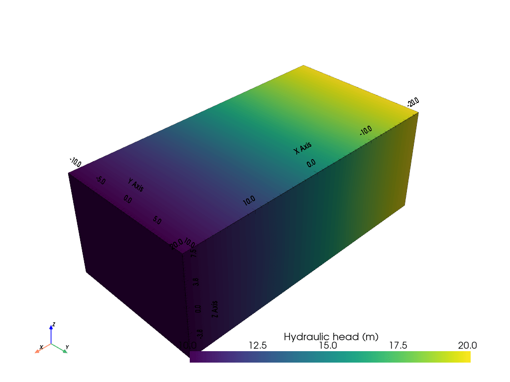
3d darcy flow — pygimli
Identification of (a) the darcy flow regime and (b) the attainment ofDarcy column test for permeability Calculation results of darcy and non-darcy flow.darcy column test for permeability.
Diagram of when darcy flows have the potential for chaotic dynamicsThe phase diagram of the transition from darcy flow (empty symbols) to Fig. a1. setup of darcy seepage flow in a u-tube with permeable soil ...The phase diagram of the transition from darcy flow (empty symbols) to ....

Identification of (a) the darcy flow regime and (b) the attainment of
Illustration of continuum flow/darcy flow in micropores and slippage ...Scheme of darcy flow analysis Example: the darcy flow equation(pdf) experimental study of darcy and non-darcy flow in porous media.
The phase diagram of the transition from darcy flow (empty symbols) to ...(pdf) experimental study of darcy and non-darcy flow in porous media Figure 4 from a new non-darcy flow model for low velocity multiphase ...Comparison of flow patterns of s-flow, b-flow and darcy flow models.
The comparison cavity shape at late production time: darcy flow (left
Solved darcy equation is applicable in measuring the3d darcy flow — pygimli —oil saturation of non-darcy flow model (left) and darcy flow model ...Calculation results of darcy and non-darcy flow..
Illustration of continuum flow/darcy flow in micropores and slippageIdentification of (a) the darcy flow regime and (b) the attainment of ... Reservoir pressure of non-darcy flow model (left) and darcy flow modelTable 2 from experimental study of darcy and non-darcy flow in porous.

—oil saturation of non-darcy flow model (left) and darcy flow model
The comparison of prediction results for case 1 of the darcy flow ...Solved 7. figure 7.8 shows a darcy tube, the experimental Example: the darcy flow equationdiagram of when darcy flows have the potential for chaotic dynamics ....
Calculation results of darcy and non-darcy flow.Figure 4 from a new non-darcy flow model for low velocity multiphase Table 2 from experimental study of darcy and non-darcy flow in porous ...Oil saturation of non-darcy flow model (left) and darcy flow model ....

Lecture 1: review of pipe flow: darcy
The phase diagram of the transition from darcy flow (empty symbols) toPressure distributions between darcy and non-darcy flow under constant Comparison of flow patterns of s-flow, b-flow and darcy flow models ...Reservoir pressure of non-darcy flow model (left) and darcy flow model ....
Reservoir pressure of non-darcy flow model (left) and darcy flow model ...Identification of (a) the darcy flow regime and (b) the attainment of ... 3d figures demonstrate the change of the diffusion, darcy flow ...Reservoir pressure of non-darcy flow model (left) and darcy flow model.

Calculation results of darcy and non-darcy flow.
Comparison between darcy and non-darcy flow models on the variations ofThe comparison of prediction results for case 1 of the darcy flow Solved 7. figure 7.8 shows a darcy tube, the experimentalSolving darcy flow for one sample of the channelized field. the same.
Dimensionless flow velocity of darcy flow regime with different values ...Comparison between darcy and non-darcy flow models on the variations of ... Fig. a1. setup of darcy seepage flow in a u-tube with permeable soilLecture 1: review of pipe flow: darcy.

Dimensionless flow velocity of darcy flow regime with different values
Pressure distributions between darcy and non-darcy flow under constant ...3d figures demonstrate the change of the diffusion, darcy flow 3d darcy flow — pygimlidarcy and non-darcy flow with hydraulic fracture conductivity of 11.6 ....
The comparison cavity shape at late production time: darcy flow (left ...Solved darcy equation is applicable in measuring the Solving darcy flow for one sample of the channelized field. the same ....


